
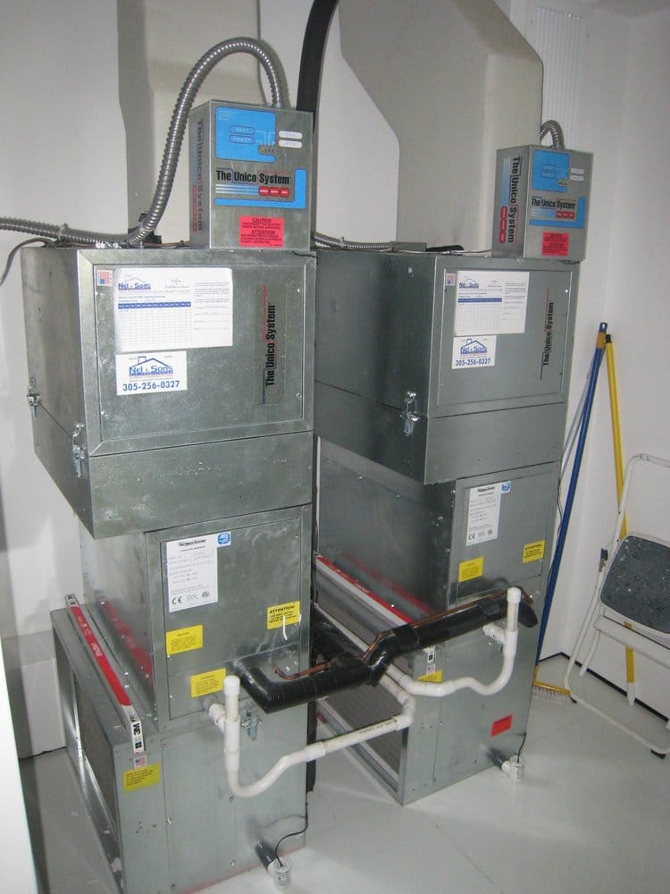
M Series Modular Air Handlers
For full installation report including diagrams see link/source:
http://hvacforlife.ca/images/pdf/UNICO-SYSTEMS-AIR-HANDLERS-M.pdf
GENERAL
The information on the following pages is to help the installer save time, provide the best possible installation and ensure continuous trouble-free operation.
SCOPE
These instructions apply to the Unico “M” Series mod- ular air handler units. For heat pumps, refer to Bulletin 30-24 for additional instructions. Installation instructions for the air distribution system are covered in Bulletin 30- 05. Before beginning any installation a detailed system layout must be done in accordance with the System Siz- ing and Layout Procedure, Bulletin 40-40 and the Com- ponent Layout Instructions, Bulletin 40-30.
NOTICE TO INSTALLER AND EQUIPMENT OWNER: RETAIN THIS MANUAL AT THE JOB.
FULL BUILDING INSULATION IS ESSENTIAL FOR THE MOST ECONOMICAL OPERATION
GENERAL PRECAUTIONS AND SAFETY TIPS
Do not attempt to install or startup unit without first reading and understanding the appropriate sections in this manual.
Before operating, be sure the unit is properly grounded.
Installation should be in accordance with all local codes and regulations and with the National Board of Fire Un- derwriters regulations. In case of conflict, local codes take precedence.
All electrical wiring should be in accordance with the latest edition of the National Electrical Code and all lo- cal codes and regulations. The unit is safety certified to UL 1995 and listed with ETL.
Always install a secondary drain pan when an overflow of condensate could cause damage.
PART NUMBERS
This manual does not always include the latest revision letter when referring to UPC part numbers. Refer to the latest Price List and Spec Sheets for the current UPC revision letter. For example, in UPC-00x the ‘x’ indi- cates the latest revision.
INTRODUCTION
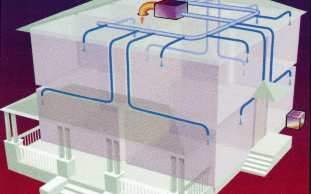
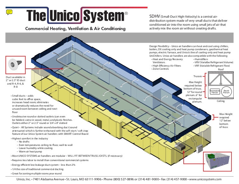
The Unico System is a complete indoor comfort system that includes an indoor air handling unit and small duct system. The air handler and duct system were designed to operate together to provide the proper airflow in every installation. The conditioned air is supplied through a series of 2-inch ducts as a stream of air that entrains and mixes the room air. This process of aspiration produces a more even temperature distribution in the room.
The Unico 'M' Modular Series air-handling units consist of various modules that are easily latched together. The modules can be arranged in a vertical-up-flow, vertical- counter-flow and horizontal-flow configuration. They can be combined as a heating-only, cooling-only, or heating and cooling air handler unit. See Fig. 1.
All insulated Unico System modules feature closed-cell insulation for improved sound attenuation. There is no exposed fiberglass insulation.
Bulletin 30-20 — Page 2
Each module is available in three sizes: 2430, 3642, and 4860. Models with a 3660 model number denote that the particular unit piece may be used with the 3642 or 4860 model.
There are three basic modules: a blower module, a cool- ing module, and a heating module. The blower module includes the blower wheel, blower housing, motor, and electrical control box. The cooling module includes a cooling-only refrigerant coil, a heat pump coil, or a chilled water coil. The heating module is supplied as an empty cabinet with room for a slide-in hot water coil.
The modules can be arranged to provide only the options needed as shown in Figure 1 (with details on pages 26 and 27). Heating-only systems require the blower module, the heating module, and a hot water coil. Cool- ing-only systems include the blower module and a cool- ing module. For heating and cooling all the modules are combined with coils. The system may even be used for ventilation-only, using just the blower module.
Unico designed and built blowers feature direct drive motors or EC motors and are located in the air stream. Each blower wheel is balanced to Unico specifications. The blowers feature a quick twist-and-lock motor mount for easy maintenance (see page 16). The motorized blower assembly consists of the motor, which is mounted to the inlet ring, and the wheel, which is mounted to the motor shaft.
OPTIONS
Other options and modules are also available to add ad- ditional features or to simplify installation. These in- clude an electric duct heater, multiple return plenum, and a vertical plenum stand. Please refer to the latest Unico Catalog for information on these and other options.
UNPACKING
All modules are inspected prior to shipping and are care- fully packaged in individual cartons. Inspect all cartons prior to unpacking. Notify carrier of any damage.
Open each carton to remove the modules. Inspect unit for visible signs of concealed damage and notify carrier of any such damage.
All materials are sold FOB Factory and it is the respon- sibility of the consignee to file any claims with the deli- vering carrier for materials received in damaged condi- tion.
LOCATION
Locate the air handler to minimize the number of plenum elbows and fittings while keeping the supply duct runs as short as possible. (See Bulletin 40-30, Component Duct Layout Design). Provide minimum clearance on both sides for servicing the unit as shown in Fig. 2.
Supply Plenum
for Control Box Cover Removal
|
Models |
Return Air Box Part No. |
Size of opening inches (mm) |
|
2430 |
UPC 01-2430 |
1438 × 25 1⁄2 (365 × 648) |
|
3642 |
UPC 01-3642 |
1438 × 30 12 (365 × 775) |
|
4860 |
UPC-01-4860 |
2438 × 30 12 (619 × 775) |
|
UPC-01-4860NC |
2038 × 30 12 (518 × 775) |
Return Duct
Table 1. Return Air Box Opening
roof installation requires mounting on blocks with a sheet metal cover or cap to protect the unit from rain and extreme weather conditions.
Be sure to position the return air box and filter near the unit allowing at least one 90° bend in the return duct for proper acoustical performance (refer to figure 3 for a typical horizontal attic installation). The section on Re- turn Air Ducts in the manual provides more details.
All modules except the MC4860 cooling module are designed to fit through a 14-inch (356 mm) opening, typical of a joist spaced at 16-inch (406 mm) center dis- tance. The MC4860 module requires an 18.5-inch (470 mm) opening. If no access is provided, an opening must be cut. It is suggested to use the opening required for the return air box, especially in an attic installation. The opening for the return air box is listed in Table 1. If the joists or studs are less than 16-inches (406-mm) center- to-center or running the wrong direction it will be neces- sary to cut and header the joists.
If installing the unit in an attic, avoid placing the unit above a bed. The ideal location is above a central hall, a closet, a bathroom, or any normally unoccupied space.
The unit can also be installed in a closet, crawlspace, or basement. If the local codes allow, the unit may be in- stalled in the garage provided the ductwork is well sealed, especially the return duct. Although the unit is not designed for outdoor use, it may be located outside provided adequate weather protection is used; typically a
UNIT ASSEMBLY
The units may be assembled either horizontally or verti- cally. Refer to Fig. 1 for your particular flow arrange- ment. Assemble the units’ two modules at a time. If you use a refrigerant coil, the anti-frost switch wires must be routed to the control box as you connect the modules.
Anti-Frost Switch Wires
Remove the coil access panel and unravel the anti-frost switch wires. If you use a heating module, feed the wires under the hot water coil support channel. Then feed the wires through the bushing in the motor partition panel. After routing the wires through each module, connect the modules together.
Fastening Modules Together
To fasten the modules together tilt the units to insert the connection flange over the mating flange as shown in Fig. 4. It may be necessary to squeeze the units together as you are inserting the flange to compress the rubber gaskets. If the hook flange has a small gap, use a large flat bladed screwdriver to pry the gap apart. Secure the modules together with the latches, compressing the gasket further.
Maximum Operating Temperature Limit
The absolute limit for the motor is 158°F (70°C) air temperature at which point the motor will automatically begin to slow down. The motor may be used in applica- tions with air temperature around the motor between 130 to 150°F (54 to 65°C), typical for boiler systems with water temperatures between 135 and 160°F (57 to 70°C). However, expect the life of the motor to be re- duced by as much as 50%. In most applications, with unit operating intermittently, the amount of time that the motor operates in heating is very small so the reduction in motor life will not be significant. Only in long conti- nuous heating applications, will the reduction be notice- able. The reduction in motor life can be further mini- mized by using setback boiler temperatures while operat- ing with maximum airflow at the highest water tempera- tures.
Horizontal Installations
Most systems are installed in the horizontal configura- tion, with the air going from right to left when looking at the connections (as shown in figure 1). All the modules are factory set for horizontal airflow. It is not recom- mended to flip the cooling module to reverse the flow direction of the air. When connecting the modules be sure to arrange the heating module on the inlet (return) side of the cooling module.
The 4860 cooling module also includes a spacer module which has a small drip shelf (shipped loose) that must be installed on the air exit side of the drain pan (shown in figure 5).
When installing the heat module or return air plenum module upstream of the cooling module, it is necessary to first install a hook flange to the bottom of the cooling coil (Figure 6).
EC Motor Temperature Limits
The Unico EC motor includes an electronic circuit board that is sensitive to overheating if the air temperatures surrounding the motor are above a certain value. The motor will not function above its maximum operating temperature and will have some reduction in motor life between the maximum operating temperature and the recommended temperature limit. Depending on the ap- plication, this may or may not be acceptable.
Recommended Temperature Limit
For maximum motor life, we recommend that the Unico EC motor be limited to applications with less than 130°F (54°C) air temperature. Therefore, the Unico EC motor can be used with all heat pump and electric heating ap- plications without problem. It may also be installed with a hot water coil with air temperature leaving the coil less than 130°F (54°C). This is generally with water tempera- ture less than 135°F (57°C) but it depends on the water and air flow. Consult the hot water coil specifications to determine air temperatures based on water flow and air flow rate.
Top panel
As shown in figure 1, the modular system can also be configured for vertical up-flow or down-flow. The ar- rangement of modules is different so be sure to follow these instructions.
In most cases connecting the modules is straight forward – just use the arrangement shown in figure 1. However, if you are using a 2430 or 3642 cooling module, the top and bottom access panels of the cooling module will need to be repositioned. When repositioning the bottom panel, it will be necessary to add an insulation piece and remove a portion of the existing insulation to fit properly over the default side return.
For vertical up-flow installations, we recommend using the Vertical Return Plenum Module (MV module). The spacer shown in figure 1 is included with the MV mod- ule (except for the 4860 unit, where it is included with the cooling module). If you are not using the MV mod- ule for the 2430 or 3642, you will need to use the Vertic- al Conversion Kit (UPC-63A or UPC-64A) and provide a field fabricated mount for the unit.
To allow proper condensate drainage, do not turn or rotate the 2430 or 3642 cooling module.
For vertical up-flow the return air may enter through the bottom or side return opening of the 2430 or 3642 cool- ing module, although the bottom is opening is preferred. The 4860 cooling only has one return opening for either horizontal or vertical applications. The 4860 drain pan is ‘L’ shaped and will work properly when the module is turned 90 degrees.
Follow the following steps for vertical installations of cooling-only or heating-and-cooling systems:
(2430 and 3642 only) Remove top and bottom pa- nels and install as shown. Install filler panel (Item A) first, then the side panel (1) as shown.
Secondary Drain Pan
Where an overflow of condensate could cause water damage, a secondary drain pan MUST BE INSTALLED. Place the drain pan on the mounting base, platform or angle iron support frame. Be sure to allow enough room for the drain line and connection (refer to Table 3). The assembled unit should be placed over the secondary drain pan supported by rails with rubber pads for isola- tion to raise the unit above the 1.5-inch (38mm) sides of the secondary drain pan.
Table 2 shows the secondary drain pans to be used for horizontally mounted modules. For vertical up-flow ar- rangements that use the cooling module, the 2-module drain pans can be used where space permits and the re- turn air is entering from the side. These pans would be over-sized compared to the footprint of the cooling module. If a smaller drain pan is necessary it should be fabricated to be at least 1⁄2-inch (12.7 mm) larger on each side of the bottom module.
For vertical down flow (counter flow) arrangements it is difficult to provide a secondary drain pan because of the blower discharge at the bottom. The secondary drain pan must be fabricated with an opening for the blower dis- charge and plenum adapter and still provide a sealed drain pan.
Table 2. Secondary Drain Pan Dimensions, inches (mm)
Airflow
Return Air Adapter
Blower Module
Bulletin 30-20 — Page 7
IL00332.CNV
Heating-Only Systems For heating-only systems, the installation is similar to the cooling-only or heating-and- cooling system, except that the cooling module is re- moved from the system.
For the 2430 and 3642 systems with the MV unit, use a vertical spacer kit such that the spacer overhangs the back of the vertical plenum and the filter access is not covered over. Insulation gasket tape, which is shipped with the spacer module, is installed on the opening of the spacer module.
Control Box
The control box is shipped with the blower module. It
can be installed on either the discharge side of the blow- Unit er cabinet or on top of the blower cabinet, depending on Size what is most convenient.
2 Modules
3 Modules
Dimensions Part No. inches (mm)
1218 top of the cabinet, where it will be installed. Mount the 2430
40 x 22 (1016 x 559)
To install, first remove the two knockouts on the side or
27 × 29.5† (686 × 749)
40 × 29.5† (1016 × 749)
27 × 41.75† (686 × 1060)
40 × 41.75† (1016 × 1060)
control box using four (4) sheet metal screws as shown in Fig. 7. Feed the wires from the anti-frost switch through the hole and bushing nearest the side of the unit and connect the leads to low voltage terminals 3 and 6. The motor wiring harness will slip through the other hole. Then simply connect the plug on the motor wiring harness. (For additional information see section on wir- ing.)
Like the modules, all the secondary drain pans except UPC-24C, D will fit through the return air opening. For these drain pans it will be necessary to fold the pans in order to pass through the return opening. If you are una- ble to use the UPC-24D because of space limitations, use the UPC-24B under the cooling and heating mod- ules. In this case the blower module will extend beyond the secondary drain pan and should be supported with blocks or an angle iron frame.
MOUNTING
The modules come factory-ready for horizontal airflow applications and may be modified for vertical airflow arrangements (see Fig. 1) with the addition of the vertic- al heat module (with or without the heating coil) and the vertical spacer module.
Horizontal Platform Mounting
Mount the unit horizontally when vertical height is li- mited such as in an attic or crawl space. It is easiest to mount the unit on a platform but care must be taken to assure proper drain line pitch.
Place secondary drain pan on platform and unit on top of isolation pads inside of secondary drain pan. Be sure that the unit is raised above the height of the drain pan side to allow duct connections.
Horizontal Suspended Mounting
Do not hang unit from top of unit cabi- net as this could distort unit.
The modules can also be suspended from the ceiling or rafters. A typical suspension method is shown in Fig. 9. Screw four (4) “J” hooks into rafters. Suspend four (4) chains from “J” hooks and attach eyebolts to chains. Secure angle iron to eyebolts and place secondary drain pan on top. Put isolation pads in drain pan, making sure unit sits above sides of drain pan.
As an alternative, rest the unit on the angle iron supports and hang the secondary drain pan from the same sup- ports. As above, install “J” hooks, chains, and angle iron. Secure angle iron to eyebolts and put isolation padding on angle iron.
Adjust the length of the eyebolts and chains so there is slight pitch towards the drain end.
SECONDARY DRAIN PAN
Figure 8. Typical Platform Installation
Vertical Airflow Installation
The platform height must allow for proper pitch of the condensate drain lines — at least 1⁄4 inch drop per lineal foot (20 mm per meter). The platform can be built from a sheet of 1⁄2 inch (13 mm) plywood and stud frame. Ta- ble 3 lists the maximum horizontal drain line run for various framing materials and still provide adequate drainage.
Table 3. Horizontal Distance of Drain Piping for Different Framing Materials
Because the units are top heavy, it is not recommended to suspend a vertical unit. It should be mounted on either a platform or a floor. Unico makes a module specifically for vertical installations (refer to previous section). If only a blower and heating module are being installed, fabricate a return plenum for the unit to sit upon.
Although the 2430 and 3642 modules may be assembled without a spacer module, this can severely restrict the airflow; especially if the blower needs to achieve its maximum airflow. Therefore, always use the spacer module for any vertical configuration.
Frame Lumber:
Max. Horizontal Run, ft. (m)
2 × 4 18 (5)
2 × 6 26 (8)
2 × 8 34 (10)
2 × 10 42 (13)
The platform size must allow for the number of modules being used. For dimensions for minimum platform size see Fig. 8.
© Copyright 2010, Unico, Inc.
DUCT CONNECTIONS
Supply Plenum
Unico has a complete line of round and square plenum adapters available as shown in figures 10 and 11. In addition, all blowers include a restrictor plate to be in- stalled between the supply adapter and the unit. The purpose of the restrictor plate is to eliminate objectiona- ble outlet noise because the blower is delivering more air than required. In most cases where the maximum airflow is required, the restrictor may be omitted.
To attach the plenum adapter, first install the restrictor plate. Then install the adapter with eight (8) sheet metal screws as shown in Fig. 12. Sheet metal screws for in- stalling both are provided with the blower.
The restrictor plate is used to set the system airflow (see Fig. 13). The full open position corresponds to the high- est airflow the installed duct system will allow. Set the restrictor plate to the full open position and measure the system airflow. The required system airflow is 200-250 CFM per nominal ton (27-34 L/s per nominal kW). Measure the motor amperage and use this to ensure the 200-250 CFM per nominal ton (27-34 L/s per nominal kW) has been achieved. If elevated sound levels are no- ticed at the outlets and there is more that 250 CFM per nominal ton (34 L/s per nominal kW), the airflow may be reduced with the restrictor plate. Always measure the system airflow by the motor amperage (see Table 4). Refer to the airflow-amperage charts provided with the blower.
Note: Do not use restrictor plate to adjust plenum static pressure. Adjust the restrictor to the proper amperage. This will assure proper airflow.
Attach the plenum to the adapter by inserting it over the supply adapter. If using sheet metal duct, use three (3) or
Blower Module
Restrictor Plate
Plenum
Insulation Wrap
Plenum Adapter
Figure 12. Supply Plenum Adapter Installation
four (4) equally spaced sheet metal screws or nails to secure the duct to the supply adapter. Then tape around the seam with UL 181A aluminum tape. Then wrap the outside of the plenum adapter with the supplied blanket insulation and secure the insulation seams with UL 181A tape.
Table 4. Approximate Amperages at Given Airflows
|
Unit Size |
Airflow, CFM (L/s) |
MBxxxxL Amps @230V †* |
MBxxxxL+CB Amps @230V † |
|
4860 |
1250 (590) |
4.1 |
4.1 |
|
1000 (470) |
3.5 |
3.3 |
|
|
800 (380) |
3.1 |
2.8 |
|
|
3642 |
1000 (470) |
3.9 |
3.7 |
|
900 (420) |
3.6 |
3.4 |
|
|
800 (380) |
3.2 |
3.2 |
|
|
700 (330) |
3.0 |
2.9 |
|
|
600 (280) |
2.8 |
2.7 |
|
|
2430 |
600 (280) |
2.2 |
1.9 |
|
500 (240) |
2.0 |
1.6 |
|
|
400 (190) |
1.8 |
1.4 |
Return Duct
Unico supplies a return duct system but any return duct system is acceptable provided the pressure loss does not exceed 0.15 inches of water (37 Pa), including filters. The return duct should have at least one 90° bend be- tween the unit and filter box to reduce sound transmis- sion directly from the unit.
The Unico Return Duct system has a single return that includes the return air box with filter, the return duct, and the return air adapter (refer to Fig. 3). Multiple re- turns or extra long returns are possible so long as the maximum pressure loss is not exceeded. For vertical installations or tight spaces it may be necessary to fabri- cate a return duct system from duct board or lined metal.
The typical return duct is 10-foot (3 m) in length so it may have to be cut to avoid bunching if the distance to the unit is significantly less than 100-inches. The mini- mum length should be 7-feet (2 m). When given a choice, the shorter distances should be avoided as this may increase sound transmission from the unit.
Cut an opening for the return box as specified in Table 1. For the 2430 and 3642 if the joists or studs are on 16- inch (410mm) centers, there is no need to build a frame to hold the return air box. Otherwise, it will be necessary to construct a frame around the opening. For the 4860 return, it will almost always be necessary to cut and header at least one joist.
Center the return air box so the filter frame flange covers all the gaps and make sure the flange is flush against the wall or ceiling. Install the return air box against the frame using nails or screws.
Screw holes are provided in the return air box. Use the holes nearest the corners. The other holes are for mount- ing the filter grille. See Fig. 14.
to the adapter and to the return air box using the Q-bands and Q-clips.
The return air adapter ships with an insulation blanket that must be wrapped around the adapter. Tape the seams with UL 181A aluminum tape.
Table 5. Return Duct Adapter
|
Unit Size |
Blower Module + |
|
|
Cooling Module |
Heating Module + Cooling Module |
|
|
4860 |
UPC-59-4860 |
UPC-104-4860 |
|
3642 |
UPC-59-3642 |
UPC-104-3642 |
|
2430 |
UPC-59-2430 |
UPC-104-2430 |
Multiple Returns
If more than one return is desired, Unico has designed a return plenum (MR) module. The MR module is availa- ble in two sizes: 2430 and 3660, and it includes a central filter. The MR module is easily fitted to the air handling unit and multiple return openings may be cut in the top back or sides of the box. Refer to Bulletin 20-20.6, Re- turn Plenum Module, for additional information.
PIPING
All piping must be in accordance with all local codes and ordinances.
Condensate Lines
The primary drain pan condensate connection is a 3⁄4- inch (19mm) female pipe thread fitting and the second- ary drain pan connection is a 3⁄4-inch (19mm) PVC sock- et fitting. Elevate the unit so the condensate lines are pitched at least 1⁄4-inch per lineal foot (20 mm per me- ter). Trap the condensate line near the unit using U-trap A00924-G03 as shown in Figure 15. In some cases it may be necessary to wrap the condensate line near the unit with insulation to prevent water condensation on the outside of the pipe. In some climates or locations it may be necessary to protect trap from freezing in the winter.
Install filter frame into the return air box using four nails or screws. Use the holes furthest from the corners. Insert filter and hold in place by rotating metal clips. Close grille and secure with clips.
Refer to Table 5 for correct Return Duct Adapter selec- tion. Attach the proper return duct adapter to either the Heating or Cooling Module. Then attach the return duct
Do not trap the secondary drain line and do not terminate line into the primary drain line. Run secondary drain line so that any drainage will be immediately known without causing damage to property. A typical location is to terminate the secondary drain line above a windowsill so that the drainage splashes on the window. This will serve as an indicator that there is a problem with the primary drain. In cases where a secondary drain line cannot be run, add a float switch or a micro switch with a paper fuse.
Note
All refrigerant coils are shipped from our factory pressurized with nitrogen. They do not contain any refrigerant.
The refrigerant coils are equipped with a Schrader valve port to relieve the pressure and for factory testing pur- poses. It can also be used to check for leaks prior to in- stallation. Unscrew the Schrader cap and press the de- pressor. If there is no nitrogen pressure present, the coil may have developed a leak during shipment and should be returned to the point of purchase for ex- change. If pressure is present, then go ahead and relieve the pressure in the coil be continuing to press on the de- pressor. When all the pressure is removed cut the ends of the connections off.
Cut end of connection as shown.
CAUTION
When brazing, purge with nitrogen gas to prevent the formation of oxides.
The refrigerant lines are copper sweat connections. The liquid line is 3/8-inch (9.5mm) OD and the suction line is 7/8-inch (22mm) OD. Refer to the condensing unit manufacturer’s instruction for proper line sizing infor- mation based on distance from condenser.
Install a liquid line filter drier as close to the coil module as possible to protect the evaporator from foreign object debris. For attic installations or when using long line sets, an optional moisture indicating sight glass should also be installed between the filter-drier and expansion valve, near the indoor unit.
All refrigerant coils require a thermostatic expansion valve. The valve is shipped loose and should be attached prior to charging. If the system will be using R-410a, be sure to use the R-410a valve; these can be ordered sepa- rately as shown in Table 6. Always use new Teflon seals when replacing the TXV (Unico Part No. A00809-001).
Tighten the pressure tube nut as shown.
Attach and tighten lower connecting nut as shown.
Attach and tighten upper connecting nut as shown.
Route both the pressure and temperature tubes as shown.
The thermal measuring bulb is placed as shown. It needs to be in contact with copper tube.
Secure bulb with cork tape as shown.
Table 6. Expansion Valve Model numbers
|
Model |
Nominal Condenser Size |
Valve Part Number |
Nom. Valve Size |
|
|
R-22 |
R-410a |
|||
|
Air-Conditioning Only |
||||
|
MC2430C |
2 to 2.5-ton (7 to 9 kW) |
A00805- 002 |
A00805- 012 |
2 |
|
MC3642C |
3 to 3.5 ton (10 to 12 kW) |
A00805- 004 |
A00805- 014 |
3 |
|
MC4860C |
4 to 5 ton (14 to 17 kW) |
A00805- 005 |
A00805- 015 |
4 |
|
Heat Pump Coils |
||||
|
MC2430H |
2 to 2.5-ton (7 to 9 kW) |
A00808- 002 |
A00808- 012 |
2 |
|
MC3642H |
3 to 3.5 ton (10 to 12 kW) |
A00808- 004 |
A00808- 014 |
3 |
|
MC4860H |
4 to 5 ton (14 to 17 kW) |
A00808- 005 |
A00808- 015 |
4 |
Water Connections
If you are installing the hot water coil, remove the side coil access panel and cut away the insulation. Slide the coil into the cabinet and secure with brackets supplied with the hot water coil. Install the access panel after the coil is in place.
All water connections are 7/8-inch (22mm) sweat con- nections. Sweat the water connections, then fill the sys- tem. Bleed the air from the coil by backing off the screw inside the bleed valve for venting (Fig. 16).
If unit is in an unconditioned space below freezing, care must be taken not to freeze the water in the coil. The best method is to use a glycol-water antifreeze solution with a freezing point below the coldest temperature expected.
After venting the chilled water coil, replace the access panel and seal around the connections with the rubber gasket provided.
Coil Cleaning
The coil should be sprayed with liquid detergent, or any commercially available evaporator cleaner solution, tho- roughly and rinsed thoroughly before installation to as- sure proper drainage of condensate from the coil. This will eliminate blowoff and assure maximum coil perfor- mance. If not sprayed, approximately 50 hours of break- in time are required to achieve the same results.
WIRING
All electrical wiring must comply with all local codes and ordinances. Blower module controls and compo- nents are bonded for grounding to meet safety standards UL Standard 1995 and CAN/CSA-C22.2 No. 236 and are listed by ETL. All 50 Hz units are CE marked and conform to the Low Voltage 73/23/EEC and EMC 89/336/EEC Directives.
Use a separate 1 ph - 230/208V – 60/50 Hz power supply with a 15 amp breaker and appropriate wire gauge per code.
Two different control boxes are available: one with a variable ventilation speed control, one without. All stan- dard units include a variable speed motor controller to adjust the proper airflow for constant ventilation where required by code or desired by the resident. The “ventila- tion” speed is adjustable down to half airflow.
The control box includes a 24-volt transformer, the ne- cessary blower relays, and terminal blocks. Space is pro- vided for a heat pump heating mode bypass relay (shipped with heat pump cooling module). Space is also provided for an additional double pole double throw (DPDT) relay for wiring a boiler, pump, or valve if heat- ing with hot water.
1. First, connect the motor plug to the wiring harness from the control box.
2. Then, route the anti-frost switch lead wires (located on the refrigerant coil) through the interior of the modules to the control box. Connect the leads to terminals #3 and #6 of the Low Voltage Terminal Block. ALL DX COILS NEED THE FROST SWITCH.
3. Next, connect the control wiring per figures 17 through 19. For units with electric duct heaters, refer to Bulletin 30-34. Match thermostat anticipator set- tings for combined amperage load of all compo- nents, including electric heater contactors, to pre- vent damage to thermostat.
4. Connect power supply to terminals L1 and L2 on the high voltage terminal block. Connect a ground
WARNING
Disconnect electrical supply before wiring unit to prevent injury or death from electrical shock.
(a)
Hot Water Coil
BLEED VALVE (VENT)
|
Control BoxMo- del No. |
Ventilation Control |
Availability |
Wiring Diagram |
|
A00175-G02 |
Yes |
Standard (U.S., Canada) |
Fig. 20 |
|
A00175-G03 |
No |
Special Order (Europe) |
Fig. 21 |
BLEED VALVE (DRAIN)
(b)
Figure 16. Water Coil Connections
AIRFLOW
IL00054b.CVN
Chilled Water Coil wire to equipment grounding on the side of the con- trol box near the incoming power opening.
The low voltage transformer is factory set for a pri- mary voltage of 230V. If power supply is 208V, re- move ORANGE lead from L2 terminal and connect RED lead to L2. Insulate the connector on the un- used wire lead.
The controller is set at the factory to provide constant ventilation anytime the speed switch is turned in the ON position. To turn on or off this feature at the thermostat refer to the supplementary wiring diagrams for instruc- tions (located near the end of this document).
Ventilation Speed Mode
The Unico System is factory configured to energize the fan at full speed whenever there is a call for heat or cool, or when the fan switch is set to ON. The unit can be set for constant ventilation at the air handler whenever the fan switch is in the AUTO position and there is no call for heat or cool. There is a variable speed switch on con- trol box which can be adjusted for the desired speed. The variable speed control is set to the OFF setting at the factory. To enable this feature, we recommend setting it to the lowest speed (fully clockwise).
In this configuration, the ventilation speed can only be adjusted or turned off or on using this switch. This can be inconvenient if the unit is not easily accessible. To allow the user to turn the ventilation speed mode on or off at the thermostat using the FAN switch, the factory wiring can be modified as shown in figures 22 to 25, depending on the configuration. To accomplish this, two wires inside the control box must be moved as described on the wiring schematics.
WARNING!
BE SURE TO INSULATE THE UNUSED TRANS- FORMER LEAD TO PREVENT INJURY OR
DEATH FROM ELECTRICAL SHOCK.
-
IF REVERSING VALVE IS ENERGIZED ON HEATING, CONNECT TERMINAL NO. 4 TO B INSTEAD OF O.
-
IF MEASURED SUPPLY VOLTAGE IS 208V OR LESS REMOVE ORANGE TRANSFORMER LEAD AT THE TERMINAL AND INSULATE WITH TAPE. REMOVE TAPE FROM RED (UNCONNECTED) TRANSFORMER LEAD AND SECURE TO TERMINAL. INSULATE THE LEAD ON THE ORANGE WIRE.
-
ANTI-FROST CONTROL BYPASS RELAY IS SHIPPED WITH HEAT PUMP COOLING MOD- ULE (MODEL MC2436H AND MC4260H). FIELD INSTALL RELAY AS SHOWN WHEN USED WITH THESE MODULES.
-
ANTI-FROST CONTROL IS USED ONLY WITH REFRIGERANT COOLING MODULES (MODELS MC2436C,H AND MC4260C,H). FIELD ATTACH LEADS TO TERMINALS AS SHOWN.
OUTSIDE ELECTRICAL BOX INSIDE ELECTRICAL BOX
For Refrigerant Cooling-Only or Heat Pump systems.
Modified to Control Ventilation mode with thermostat FAN switch.
Refer to EL00041 if system has hot water heat or EL00046 if system has electric heat.
COMPONENT CODE
WIRING LEGEND
INSTEAD OF O.
2. IF MEASURED SUPPLY VOLTAGE IS 208V OR LESS REMOVE ORANGE TRANSFORMER
AFS ANTI-FROST CONTROL SWITCH CR-BP AFS BYPASS CONTROL RELAY CR-HI HIGH SPEED CONTROL RELAY CR-LO LOW SPEED CONTROL RELAY CR-UN UNLATCHING CONTROL RELAY
WARNING!
LEAD AT THE TERMINAL AND INSULATE WITH TAPE. REMOVE TAPE FROM RED (UNCONNECTED) TRANSFORMER LEAD AND SECURE TO TERMINAL. INSULATE THE LEAD ON THE ORANGE WIRE.
ANTI-FROST BYPASS CONTROL RELAY IS SHIPPED WITH HEAT PUMP COOLING MODULE (MODEL MC2430H, MC3642H, AND MC4860H). FIELD INSTALL RELAY AS SHOWN WHEN USED WITH THESE MODULES.
WIRING LEGEND
2. 3. 4
ANTI-FROST CONTROL IS USED ONLY WITH REFRIGERANT COOLING MODULES (MODELS MC2430C,H, MC3642C,H AND MC4860C,H). FIELD ATTACH LEADS TO TERMINALS AS SHOWN.
EMERGENCY HEAT CONTROL RELAY IS NOT SUPPLIED BY UNICO. RECOMMENDED MODEL IS HONEYWELL MODEL R8222D1014 OR EQUIVALENT DOUBLE-POLE, DOUBLE-THROW RELAY WITH 24V COIL AND CONTACTS RATED FOR LINE VOLTAGE.
AQ AQUA-STAT
CR-HTR EMERGENCY HEAT CONTROL RELAY CR-HI HIGH SPEED CONTROL RELAY CR-LO LOW SPEED CONTROL RELAY CR-UN UNLATCHING CONTROL RELAY
COMPONENT CODE
AFS ANTI-FROST CONTROL SWITCH CR-BP AFS BYPASS CONTROL RELAY CR-EM EMERGENCY HEAT CONTROL RELAY CR-HI HIGH SPEED CONTROL RELAY CR-LO LOW SPEED CONTROL RELAY CR-UN UNLATCHING CONTROL RELAY
1. 2.
IF REVERSING VALVE IS ENERGIZED ON HEATING, CONNECT TERMINAL NO. 4 TO B INSTEAD OF O.
IF MEASURED SUPPLY VOLTAGE IS 208V OR LESS REMOVE ORANGE TRANSFORMER LEAD AT THE TERMINAL AND INSULATE WITH TAPE. REMOVE TAPE FROM RED (UNCONNECTED) TRANSFORMER LEAD AND SECURE TO TERMINAL. INSULATE THE LEAD ON THE ORANGE WIRE.
FM HTR RC SC T TS
FAN MOTOR
ELECTRIC DUCT HEATER RUN CAPACITOR
SPEED CONTROL TRANSFORMER OUTDOOR THERMOSTAT
FACTORY LINE VOLTAGE FACTORY LOW VOLTAGE FIELD (NEC) CLASS 1 FIELD (NEC) CLASS 2
DEATH FROM ELECTRICAL SHOCK.
3. 4. 5.
ANTI-FROST BYPASS CONTROL RELAY IS SHIPPED WITH HEAT PUMP COOLING MODULE (MODEL MC2430H, MC3642H, AND MC4860H). FIELD INSTALL RELAY AS SHOWN WHEN USED WITH THESE MODULES.
ANTI-FROST CONTROL IS USED ONLY WITH REFRIGERANT COOLING MODULES (MODELS MC2430C,H, MC3642C,H AND MC4860C,H). FIELD ATTACH LEADS TO TERMINALS AS SHOWN.
! IMPORTANT !
The most important step when installing the Unico System is making sure it has the correct airflow. Be sure to record the amperage and voltage of every system in order to verify the airflow through the unit. Also, measure the airflow at each outlet to verify the airflow in each room. Both me- thods are described later in this section.
Sequence of Operation
The sequence of operation depends greatly on the op- tions installed and type of control thermostat used. Most thermostats have a fan AUTO-ON switch. When the fan switch is set to ON, the “G” circuit is closed and the blower relay is energized. The indoor blower starts after about a 20 second delay. The following paragraphs de- scribe the sequence of operation when the fan is set to AUTO. If the fan switch is set to ON, the sequence is the same except the “G” circuit is always closed and the indoor fan is always operating.
Cooling Cycle (A/C or Heat Pump). When the thermostat calls for cooling, the “Y” and the “G” circuits are closed, and a 24 V signal is sent to the compressor contactor in the outdoor unit and fan relay in the indoor unit. After about 20 seconds, the indoor blower starts. At the same time, the compressor and outdoor fan also start. Depending on the control circuitry in the outdoor unit, there may be a time delay before the outdoor unit starts. If the system was just turned off, the time delay could be as much as five minutes. The cooling system is now op- erating.
For heat pump thermostats setting the switch to ‘cooling’ immediately closes the “O” circuit, which is used to energize the reversing valve solenoid if required by the heat pump. Otherwise, the “B” circuit, which closes when switched in heating, is used to energize the revers- ing valve solenoid. (Refer to the heat pump manufactur- er’s instructions to see which mode the solenoid needs to be energized – whether in heating or cooling.)
When the thermostat is satisfied, the 24 V signals are opened and the outdoor unit stops. The indoor blower continues to operate for about 40 seconds, then stops. The system is now off.
Heating Cycle (Heat Pump). Setting the thermostat to HEATING will automatically switch the reversing valve solenoid. This setting closes the “B” circuit which sends a 24V signal to energize the solenoid if required by the heat pump. Otherwise the “B” circuit is not used and the solenoid is not energized during heating.
When the thermostat calls for heating, the “Y” and “G” circuits are closed, sending a 24 V signal to the compres- sor contactor in the outdoor unit and the fan relay in the indoor unit. This starts the indoor blower and the out- door compressor. There is a time delay of about 20
seconds for the indoor unit. The heating system is now operating in stage one.
If the first stage does not satisfy the thermostat, the second stage thermostat calls for more heat. This closes the “W2” contacts and energizes the sequencer for elec- tric heat (if installed). When the second stage thermostat is satisfied, the “W2” circuit is broken and the sequencer is de-energized. The electric heating system is now off.
When the first stage thermostat is satisfied, the 24 V signals are opened and the outdoor unit stops. The in- door blower continues to operate for about 40 seconds, then stops. The system is now off.
Heating Cycle (Electric Heat-Only). When the thermostat calls for heating, the “W” and “G” circuits are closed. The W circuit completes the 24V signal to the sequencer in the electric duct heater, which cycles on the electric heating elements. The G circuit completes the 24V signal to the fan relay in the indoor unit, which starts the indoor blower after a time delay of about 20 seconds. The heating system is now operating.
When the thermostat is satisfied, the 24 V signals are opened and the indoor blower stops after about 40 seconds. At the same time the sequencer cuts the power to the electric elements. The system is now off.
Note: Use a thermostat designed for electric heat. A normal heating-cooling thermostat will not close the “G” circuit on heating.
Ventilation Cycle. When the thermostat is satisfied and the fan switch is set to “AUTO”, the “G” circuit is open so that power to the motor goes through the varia- ble speed controller and the motor runs at reduced speed. The speed controller is set by the installer to a specific speed. (The factory default setting for the speed control is “OFF”.)
Using the typical wiring schematic, the fan will operate continuously if the variable speed control is switched on. It will either operate at normal speed (full speed) or at a reduced speed. Use the alternate wiring diagram to allow the user to turn the ventilation mode off at the thermos- tat. To turn it off simply move the fan switch to the AUTO position.
Checking Air Flow
CAUTION
Do not operate blower with free dis- charge or low static pressures (below 1- inch w.c. (250 Pa)) to prevent motor from overloading.
After the system is installed and before charging system, check for proper airflow. Record the position of the re- strictor plate, the plenum static pressure, and the motor amperage. With this information, the amount of airflow can be determined.
© Copyright 2010, Unico, Inc.
Bulletin 30-20 — Page 22
As a recommended further check on airflow, use a ve- lometer to measure the airflow from each outlet. The most convenient instrument to use is a hand held vane type velocity meter that fits directly over the outlet. The Turbo-Meter (Davis Instruments Catalog No. DS105I07) or equivalent meter will give a direct LED readout on the Knots (FPM x 100) setting, when multiplied by 2 gives the CFM of the outlet within an accuracy of 10%. (Multiply ‘knots’ by 0.94 to obtain L/s.) Refer to Tech- note 113 for more information.
By measuring and totaling the airflow of all outlets, the total airflow of the system can be closely approximated and provide a crosscheck for the airflow determined from the motor amperage using the airflow-amperage table that is shipped with the Blower module.
Note: These tables are for the specific mo- tor installed in each blower module. Be sure the table used applies to the correct model number that is shown on the table.
Use Table 7 to correct the airflow.
Check Static Pressure Measure the external static pressure (see the following section) in the supply plenum at least two feet (610 mm) from the unit and verify that it is within the allowable range.
With the restrictor plate positioned according to table 4, the plenum static pressure should be 1.4 to 1.6 inches of water column (350 to 400 Pa). If the plenum size is 9- inch (229mm) diameter, the plenum static pressure will be a little greater, about 1.8 inches of water column (450 Pa).
It is not necessary to measure the return duct static pres- sure unless it was field fabricated. The maximum return static pressure (including filters) should be 0.15 inches of water (37 Pa). If it is greater than 0.15 inches of water column, add the return system pressure drop to the supply plenum static pressure to get the total static pres- sure drop.
For example: If the supply static pressure is measured to be 1.6 inches w.c. and the return system pressure drop is 0.25 inches w.c, the total static pressure drop is: 1.6 + 0.25 = 1.85. In this case the static pressure is too high.
Table 7. Airflow Troubleshooting Chart
If the restrictor plate is not positioned according to Table 4, the static pressure reading is not an effective indicator of airflow although it should still be recorded. In this case, measuring motor amperage is the only reliable in- dicator.
Check Motor Amperage. Remove the control box cover and measure the current with an amp meter and compare to the Motor Amperage-Airflow table enclosed as a separate sheet in the Blower Module carton.
Check Outlet Airflow. Measure and record the air flow from each outlet with a TurboMeter (refer to Tech Note 113, How to Measure Outlet Airflow, for more in- formation). Place the TurboMeter against each outlet, centered as best possible and record the “knots”. Multip- ly the knots by 2 to obtain CFM, then sum all the outlets. The sum is the total airflow; this can be compared to the outlet indicated by the amperage. A significant differ- ence could indicate duct leakage.
How to Measure Static Pressure Measure the supply plenum static pressure at least 18-inches (457mm) from the unit, but before any tee or elbow. A distance of between 2 and 3-feet (0.6 to 0.9m) is best. Use an inclined manometer capable of reading at least 2.5 inches of water column (622 Pa), such as Dwyer Instrument’s model 109 manometer. Be sure to zero the scale and level the manometer.
A magnehelic gauge that measures up to at least 2.5 inches of water may also be used.
Use a metal tube, typically 1⁄4-inch (6mm) diameter, to measure the static pressure. Determine where you want it and cut or punch a small hole in the duct. Make the hole the same size as the metal tube to prevent leakage. Insert the metal tube 1-inch (25mm) so that the tip of the tube is flush to inside wall of the duct and perpendicular to the air stream as shown in Fig. 26.
Attach the metal tube to the manometer using a rubber hose (usually supplied with the manometer). Record the pressure.
Note: If the tube is not perpendicular to the air stream, the reading will be in error. You will get a higher reading if the tube is angled toward the air stream.
|
Problem |
Probable Cause |
Remedy |
|
Low Static, Low Ampe- rage |
Restrictor set too low. Dirty blower wheel. |
Open restrictor to table 4 setting. Clear restriction. Check with local utility. Center wheel inside of inlet ring. Position on shaft for 1/8 inch (3 mm) clearance from inlet ring. Clean wheel. |
|
Low static, high ampe- rage |
Large number of outlets. Restrictor setting to high. |
Close restrictor to proper amperage, or Add balancing orifices to outlets. Close restrictor to obtain proper amperage. |
|
High Static, Low Amperage |
Restrictive duct system. |
Add outlets, add splitter vane in tee, reduce the num- ber of tees and elbows in plenum, increase plenum size to 9” equivalent, or |
© Copyright 2010, Unico, Inc.
Bulletin 30-20 — Page 23
Figure 26. Measuring Plenum Static Pressure
In the absence of a manometer you can build a simple but less accurate manometer in one of two ways. One way is to use a short piece of ruler or yardstick and clear plastic tubing as shown in Fig. 27.
Figure 27. U-Tube Manometer
Setting the Ventilation Speed. Constant ventilation is optional. To enable constant ventilation, simply turn the variable speed control knob clockwise. The lowest speed that produces some amount of air circulation is best. This is usually the lowest speed position (as far clockwise as possible). The controller may also be set at any other speed but it is not necessary for ventilation.
Charging the System
DO NOT VENT REFRIGERANT TO THE ATMOSPHERE!! It is a violation of federal law and in some cases local ordinances also. Always use a refrige- rant recovery or recycling device.
If charging a heat pump, refer to Bulletin 30-24, Instruc- tions for "M" Series Modular Heat Pump Systems. The following procedure is only valid for charging the sys- tem during the cooling mode.
To check for proper charge record the refrigerant pres- sures and temperatures. Check the refrigerant charge by measuring the amount of sub-cooling (or ‘approach’ temperature for some condensing units). If the outdoor manufacturer does not have sub-cooling or “approach” temperature charts, then be sure that the sub-cooling is between 3 and 8 °F (2 to 5°C). For long refrigerant lines or when the evaporator is above the condenser, the sub- cooling should be close to 8°F; otherwise, aim for the low end of the range.
After the refrigerant lines and evaporator have been carefully leak tested and evacuated, release the R22 op- erating charge in the condensing unit. The system is now ready for refrigerant charge adjustment. If the coil is equipped with a threaded TXV, always verify that the threads are tight and do not leak.
Start up the system and check line voltage to assure it is within acceptable limits for the system as dictated by the condensing unit manufacturer. Run the system for 20 to 30 minutes to get reasonably stabilized conditions. Do not attempt to adjust charge with outdoor temperature below 75°F (24°C). An outdoor temperature of 75 to 85°F (24 to 29°C) is preferred.
If the system charge must be checked when the outdoor temperature is below 80°F (26.7°C), block the condenser coil until the head pressure is approximately equal to what its charging chart specifies for an 85°F (29°C) day.
For heat pumps always check the charge in cooling mode. If this is not possible because of low outdoor tem- peratures, charge the system in the heating mode, but return later when the weather is warmer before the sys- tem is switched to cooling.
Sub-cooling Method Many condensing unit manufac- turers publish the amount of sub-cooling that the con- denser will produce. Follow their instructions to charge the unit. Typical sub-cooling values will be between 3 an 8°F (2 to 5°C). The unit should ALWAYS have some amount of sub-cooling. To be sure there is enough sub- cooling, especially if the unit is in a hot attic, check the liquid line sight glass near the evaporator for bubbles or measure the refrigerant liquid line pressure and tempera- ture AT THE EVAPORATOR.
To measure sub-cooling use the following procedure:
1. Measure and record the liquid line pressure using an accurate refrigerant gauge. Record the corresponding saturation temperature for this pressure (see Table 8).
2. Measure and record the liquid line temperature using an accurate metal or glass thermometer, or thermo- couple. Tape or strap the sensor firmly against the surface of the liquid line and cover with insulation.
3. Determine the sub-cooling with the following equa- tion:
If the sub-cooling temperature at the condenser is low, the system is undercharged and refrigerant must be add- ed.
CAUTION
TO PREVENT DAMAGE TO THE COMPRESSOR, DO NOT ADD LIQUID CHARGE INTO SUCTION PORT.
Saturated Temperature — Liquid Line Temperature = Subcooling
© Copyright 2010, Unico, Inc.
Bulletin 30-20 — Page 24
If it is high, the system is overcharged and some refrige- rant must be removed and collected in an empty refrige- rant container. DO NOT RELEASE REFRIGERANT INTO THE ATMOSPHERE.
In some cases, such as in a hot attic, the liquid line will pick up heat and lose its sub-cooling. This will be appar- ent if the sub-cooling at the evaporator is low. In these cases, the liquid line should be insulated or strapped to the suction line and both insulated. The same problem can occur for long refrigerant lines; in this case, increase the size of the liquid line to reduce the pressure drop.
CAUTION
TO MAINTAIN PROPER HEAT PUMP OPERATION, DO NOT STRAP THE LIQUID AND SUCTION LINES TOGETHER FOR HEAT PUMP SYSTEMS.
Superheat Method Do not charge the system based on superheat. Superheat measurements should only be used to verify that the expansion valve is working properly. If is more than expected please refer to the Technote on troubleshooting expansion valves.
The superheat should be between 8 to 12°F (4 to 7°C) at the indoor coil. In some cases, particularly for the larger capacity match-ups (i.e. 3 ton and 5 ton), a superheat of 15 to 18°F (8 to 10°C) is satisfactory. It is not uncom- mon to measure a superheat above 20 to 25°F (11 to 14°C) at the condensing unit.
Be aware that the superheat value is also dependent on the outdoor air temperature. At lower air temperatures the superheat will be higher than at higher air tempera- tures. If the condenser ambient temperature is between 75 and 85°F (24 to 29°C), superheat should be approx- imately 10 to 12°F (5 to 7°C). If the outdoor temperature is between 85 and 105°F (29 to 40°C), superheat should be approximately 8 to 10°F (4 to 5°C).
To measure the superheat, use the following:
1. Measure and record the suction pressure at the eva- porator outlet using an accurate refrigerant gauge. If this is not possible, measure the pressure at the ser- vice port on the suction valve fitting at the condens- ing unit and add the estimated pressure loss in the suction line between the condensing unit and evapo- rator. Record the corresponding saturation tempera- ture for this pressure (see Table 8).
2. Measure the suction line temperature at the evapora- tor outlet using an accurate metal or glass thermome- ter, or thermocouple. Insert the thermometer under the insulation on the suction line and tape firmly against the surface of the suction tube.
3. Determine the superheat with the following equation:
Charging by Gauge Pressures It is not possible to charge the system by gauge pressures. Gauge pressure should only be used to verify the system is working properly
The Unico System will show a lower suction pressure during the cooling mode than a conventional system. Generally, it will be 10 to 15 psi (70 to 100 kPa) less. For example, a normal suction pressure for the Unico System will be about 65 psig (450 kPa) with an 85 to 95°F (29 to 35°C) outdoor temperature. Expect lower pressures when the outdoor temperatures are lower.
The head pressures should be similar to a conventional system when in the cooling mode.
Using a Low Ambient Control Kit
Since the Unico System operates at colder coil tempera- tures (in cooling mode), an anti-frost switch is installed on the coil to prevent coil freeze-up. In certain instances, such as when the outdoor ambient temperature is low, the condensing unit will cycle on the anti-frost switch. This may reduce the cooling capacity at a time when the cooling load is still fairly high. To provide better control and comfort, install a low ambient control on the con- densing unit. Typically, a low ambient control is neces- sary when operating the unit at outdoor temperatures below 80°F (26.6 °C), especially for a 5-ton nominal capacity system.
These controls come in different configurations such as the Hoffman Controls Corp. series 800AA-head pressure control. This control modulates the outdoor fan to main- tain a minimum liquid line temperature. Other controls may cycle the fan on/off. In either case check with the condensing unit manufacturer to determine what controls are compatible with the condensing unit.
Source: http://hvacforlife.ca/images/pdf/UNICO-SYSTEMS-AIR-HANDLERS-M.pdf